Optimizing Scan Speeds and Signal to Noise Ratio for ECA Inspections
By Jesse Herrin, Zetec Product Manager – Eddy Current Systems

With eddy current array (ECA) technology, there is a direct relationship between scan speed and signal to noise ratio (SNR).
SNR is a measure of the level of a desired signal to the level of background noise in the scan. A low SNR limits the ability to detect the very small flaws and loss of material that can occur in friction stir welds and multi-layer structures.
As scan speed increases, the SNR decreases. Conversely, slower scan speeds are more likely to raise the SNR and produce the required probability of detection (POD), but they take more time.
The question for eddy current technicians becomes how to calculate a scan speed that will produce the required POD while completing the inspection in a cost-effective manner compared to other nondestructive testing methods?
How to calculate scan speeds
The theoretical maximum scan speed for an ECA probe is the time-slot rate (TSR) divided by the product of the spatial resolution (SPR) and number of time-slots (TS). A common SPR is 2 samples/mm. The theoretical maximum scan speed is not practical for ECA applications that demand high signal quality because the processing time of the eddy current signal is not long enough to reject noise that is present.
Practical sample rate (SR) for ECA applications is much lower than the theoretical maximum to allow enough processing time to produce lower noise signal. This makes high SR superfluous for ECA.
The SNR of the array probe data is an inverse function of the SR. The maximum SR will result in the worst SNR. Slowing down the SR will achieve better SNR by stretching the periods of the TS to average more samples. This will improve the detectability of small flaws. The SNR will improve by 3 dB each time that the sampling rate is cut in half. For example, a scan speed of 200 mm/sec will have an SNR that is 3 dB better than a 400 mm/sec scan speed. Slowing the scan speed down to 100 mm/sec (one-fourth) will produce an SNR that is better by 6 dB.
SNR filtering with software
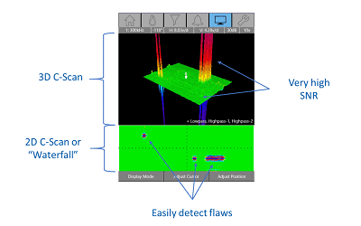
Software that supports single- and dual-frequency eddy current, rotating scanners and conductivity with the viewing tools of Impedance, Sweep, Waterfall and C-Scans can help maximize an instrument’s ability to manage SNR and deliver an accurate, detailed inspection result.
Another software feature, SNR filtering, allows the technician to filter off low-level voltage signals and retain data above a specified range. This filter looks for and reduces the noise in the data without attenuating the real signals of interest—essentially, it lowers the “N” or noise part of the ratio without affecting the “S” or signal part.
This differs from a threshold filter, which will remove everything below a certain point, including signals of interest. An SNR filter can be activated while acquiring data or, importantly, after acquisition for further analysis.
Conventional NDT methods can be time consuming, and inspections that are quick to set up and complete while delivering a high probability of detection add value. With an ECA instrument and surface array probe—and an understanding of SNR—you can provide the right balance of inspection speed, detection capability and cost effectiveness.
Zetec is a global leader in nondestructive testing (NDT) solutions for the critical inspection needs of industries the world counts on every day. To learn more, contact Zetec today!