Improve Speed and Detection Probability in Aerospace Friction Stir Weld Inspections

By Daniel Richard, Zetec UT Technology Manager
Friction stir weld (FSW) inspections in aerospace manufacturing are challenging not because they require complex techniques but because scanning with conventional probe setups can be so time consuming.
Speed is essential to fabricators. Properly calibrated, an FSW machine can quickly produce long runs of clean, continuous, fully compacted bonds. Aerospace manufacturers value inspections that are quick to set up and complete while delivering a high probability of detection.
With a portable phased array ultrasonic testing (UT) instrument and dual (2D) matrix array probe assemblies, nondestructive testing (NDT) technicians can build efficient scan plans, conduct lateral scans and create three-dimensional representations of the weld, and detect mis-oriented and transverse flaws in lap and butt welds.
Covering the entirety of the weld with phased array UT requires multiple beam angles, however, which can add steps to the inspection process.
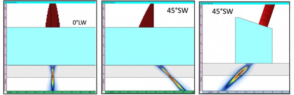
For a butt-joint weld, the recommended technique for transverse flaws involves linear electronic scanning with two different refracted angle orientations: a +45° shear wave and a symmetrical -45° shear wave (+20° and -20° incident wave angles in immersion).
In the case of a lap-joint weld, the same two beam angles (+45°SW and -45°SW) are used in conjunction with a 0° longitudinal wave, which is the ideal angle for detecting joint-line flaws.
Performing the inspection with a standard single 64-element probe requires multiple setups and scanning sequences. A lap-joint inspection would involve separate sequences at +45°SW, 0°LW, -45°SW, with the technician stopping in between scans to realign and recalibrate the probe. A butt joint would require two separate scans at +45°SW and -45°SW.
Interrupting the test to manipulate the probe orientation every time another refracted angle is required is tedious but necessary due to the limited steering capability of a probe that’s not designed for FSW inspections.
Optimized Solutions
Zetec has developed a 1D linear array probe with 128 elements that can simultaneously generate 0°LW and 45°SW beams for flaws parallel to the weld center line without probe inclination, and 45°SW for detection of transverse flaws when inclined in the secondary plane.
Used with a TOPAZ portable phased array UT instrument, this type of optimized probe can obtain full volumetric coverage of the weld zone in a single scanning sequence and allow better detection of skewed flaws and accurate sizing compared to other solutions.
In an effort to demonstrate the efficiency of such a probe, Zetec engineers generated a side-by-side comparison of scan results obtained by using a 10 MHz, 64-element probe and the optimized probe on an aluminum test plate with notches.
At a frequency of 7.5 MHz, the FSW-optimized solution demonstrates more accurate length sizing and a reduced noise level, an improved lateral beam spread, and a greater tolerance to the rough surface conditions of a stir weld. Another consideration is the reduced presence of undesirable artifacts in the signal.
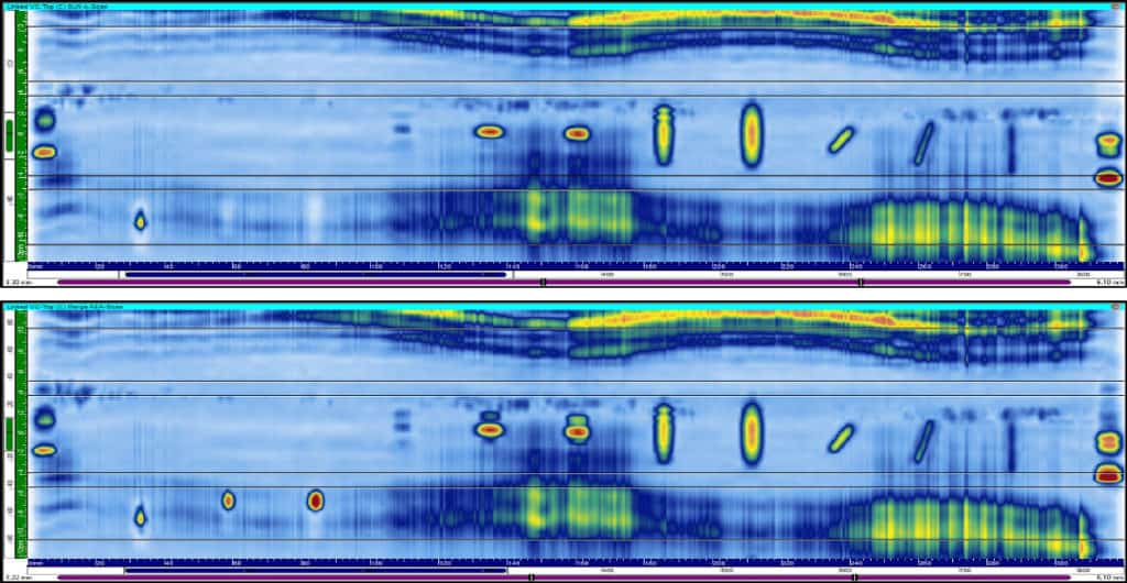
The same specimen was also subjected to a 0°LW scan. In figure 1, the bottom image shows a merged view of all data groups—0°LW and ±45°SW—and demonstrates more accurate length sizing and reduced noise level.
Because all required refracted angles are generated with a single probe positioned at a normal incidence with respect to the inspected specimen surface, this alone simplifies the probe installation and alignment method since all that’s now required is to install it in the 0° scanner head.
Once the probe orientation is set, the 10 MHz, 64-element probe with one single UT channel configuration has an acquisition rate of approximatively 60 Hz, meaning an inspection speed of 60 mm per second with a 1 mm displacement increment per second.
For a complete setup, including three channels at ±45°SW and 0°LW at maximum linear resolution, the optimized system can reach a speed of 30 mm per second. However, the optimized solution has three channels instead of one, which is the equivalent to three passes with the other probe. The linear resolution is greater, meaning more data is acquired. If the resolution is modified to match the 0.5 mm of the 64-element probe, it’s the equivalent to doubling the probe’s speed. Moreover, the optimized system streamlines the inspection time compared to the standard probe because the setup is simpler.
If even faster inspection speeds are required, two optimized probes can be used on two units in parallel to reach up to 50 mm per second at maximum resolution, or three pairs can be used for up to 100 mm per second. As with any multi-instrument or multi-probe solution, the tradeoff is additional cost and complexity.
Aerospace is an industry where productivity and cost control are a constant focus. The combination of a TOPAZ portable phased-array UT instrument and a dedicated probe for FSW inspections can deliver the rapid setup, quick calibration, and faster inspection speeds aerospace manufacturers expect.
Zetec is a global leader in nondestructive testing (NDT) solutions for the critical inspection needs of industries the world counts on every day. To learn more, contact Zetec today!